BGFX vector CRT renderer
Purpose and status
The BGFX vector CRT renderer is a GPU pipeline for MAME vector games. It replaces direct, frame-oriented line drawing with a persistent HDR phosphor buffer, instanced Gaussian beam deposition, approximate scan-order timing, bloom, and tone-mapped composition.
The bgfx_vectorcrt option is enabled by default; set it to 0 to disable
it. The renderer is used only with the BGFX video backend and when the
primitive list contains a vector-buffer marker. If its effects, geometry, or
RGBA16F render targets cannot be created, BGFX falls back to normal vector line
rendering.
Source map
The implementation is split across these locations:
src/osd/modules/render/bgfx/vectorrenderer.cppand.hmanage render targets, instance generation, pass scheduling, emulation time, and sliders.src/osd/modules/render/drawbgfx.cppand.hintegrate the renderer, intercept vector primitives, preserve draw ordering, and composite output.src/osd/modules/render/bgfx/shaders/chains/vector-crt/contains shader source and varying definitions.bgfx/effects/vector-crt/contains render state, uniforms, samplers, and shader program selection.bgfx/shaders/<backend>/chains/vector-crt/contains compiled shaders for Direct3D 9, Direct3D 11, OpenGL ES, OpenGL, Metal, and SPIR-V.
Pipeline overview
Ordered MAME vector primitives
            |
            v
CPU instance buffer (one record per segment)
            |
            v
Previous RGBA16F accumulation -- exponential decay --+
                                                       |
Instanced Gaussian beam deposition --------------------+
            |
            +----> persistent full-resolution phosphor
            |
            v
Half-resolution box downsample
            |
            v
Two horizontal/vertical Gaussian blur iterations
            |
            v
Phosphor + bloom -> exposure -> tone map -> gamma -> output
The persistent accumulation is ping-ponged between two full-resolution RGBA16F targets. Bloom uses two RGBA16F targets rounded up to half the output dimensions:
bloom_width  = max(1, (width  + 1) / 2);
bloom_height = max(1, (height + 1) / 2);
RGBA16F is required because additive beam contributions must retain HDR energy across frames before tone mapping.
Integration and frame ordering
renderer_bgfx creates bgfx_vector_renderer when bgfx_vectorcrt is
enabled. At the start of a frame, prepare() scans the primitive list:
PRIMFLAG_VECTORBUFidentifies a vector screen and activates the renderer.Line primitives with
PRIMFLAG_VECTORare collected in display-list order.
These vector lines are omitted from normal BGFX line batching. The completed CRT image is composited where the vector-buffer marker occurs, preserving its order relative to artwork and other primitives.
Each active frame performs the following operations:
Decay or clear the persistent phosphor target.
Add all vector beam instances to the same target.
Downsample the phosphor image into the first bloom target.
Apply two iterations of horizontal and vertical bloom blur.
Composite persistent phosphor and bloom into the configured BGFX view.
Views use sequential mode because later passes consume textures written by earlier passes.
Time and phosphor persistence
The renderer uses emulated time rather than wall-clock time:
The first frame assumes 1/60 second.
A repeated or effectively zero timestamp is ignored, preventing repeated excitation of the same display list while paused.
Backward time after reset, state load, or rewind clears the accumulation.
A forward interval is capped at 0.100 second to avoid extreme pass values.
For frame interval dt and persistence time constant tau, the decay pass
applies:
decay = exp(-dt / max(tau, 0.001))
I_next = I_previous * decay
This is inter-frame phosphor decay. Scan-order attenuation within newly drawn geometry uses a deliberately gentler lifetime described below.
CPU instance generation
Every vector segment becomes one 12-float instance:
struct beam_instance
{
    float x0, y0, x1, y1;       // target-pixel endpoints
    float red, green, blue;      // beam colour
    float sigma;                 // Gaussian sigma in target pixels
    float start, duration;       // normalised display-list scan interval
    float intensity;             // primitive alpha
    float unused;
};
The instance vectors seen by the vertex shader are:
i_data0 = (x0, y0, x1, y1)
i_data1 = (red, green, blue, sigma)
i_data2 = (start, duration, intensity, unused)
Approximate scan timing
The implementation does not receive hardware beam timestamps. It approximates constant deflection speed using accumulated segment length:
length = max(endpoint_distance, max(primitive_width, 1 pixel))
start = elapsed_length / total_length
duration = length / total_length
The width/one-pixel lower bound gives points and degenerate segments a non-zero dwell interval. This preserves display-list order but does not account for blanked moves, hardware slew limits, or vector-generator timing.
Beam width and resolution scaling
The CPU converts MAME line width to Gaussian sigma with an empirical profile calibration:
constexpr float BEAM_SIGMA_SCALE = 0.085f;
sigma = primitive.width * m_beam_width * BEAM_SIGMA_SCALE;
0.085 is not a resolution scale or the standard Gaussian full-width at
half-maximum conversion. It was calibrated for the desired appearance. If
primitive.width were interpreted as Gaussian FWHM, the conversion would be
sigma = width / 2.35482. That would produce a materially different profile
and require retuning.
primitive.width is already in target pixels. MAME constructs it in
render_target::add_container_primitives() by multiplying normalised line
width by the smaller target-space scale:
prim->width = curitem.width()
        * std::min(container_xform.xscale, container_xform.yscale);
For the same view and aspect ratio, primitive.width doubles from 1080p to
2160p. Beam width therefore scales with the rendered screen item, including
layout and letterboxing. Applying another height / 1080 factor to sigma
would double-compensate.
Bloom differs because its radius originates as a UI pixel value referenced to 1080 lines, so it requires an explicit resolution scale.
Beam shaders
Vertex stage
The shared mesh is a six-vertex unit quad. vs_beam.sc expands it around
each segment in target-pixel space:
Compute segment direction, perpendicular normal, and length.
Extend both endpoints by
max(6 * sigma, 1 pixel).Emit the padded quad through a target-pixel orthographic projection.
Pass beam-local
alongandacrosscoordinates to the fragment shader.
Six sigma contains the useful Gaussian tails. Longitudinal padding provides
pixels for round endpoint caps. Zero-length segments use (1, 0) as a
stable fallback direction.
Intensity-dependent profile
Intensity is primitive alpha. Its response is compressed before it affects beam shape:
intensityResponse = sqrt(clamp(intensity, 0, 1))
coreSigma = baseSigma * mix(1.00, 1.12, intensityResponse)
haloSigma = baseSigma * 3.5 * mix(1.00, 1.25, intensityResponse)
haloStrength = haloControl * mix(0.6, 1.0, intensityResponse)
The profile is a Gaussian core plus a wider, weaker halo. Outside the segment endpoints, longitudinal and perpendicular distance are combined for round caps:
pastEndpoint = max(-along, along - beamLength, 0)
distanceSquared = across^2 + pastEndpoint^2
Pixel-footprint filtering
Very narrow analytic Gaussians alias if sampled only at pixel centres. The
fragment shader approximates a pixel as a box filter. For footprint
pixelAcross, box variance is pixelAcross^2 / 12 and is added to beam
variance:
filteredSigma = sqrt(sigma^2 + pixelVariance)
The peak is multiplied by sigma / filteredSigma so broadening does not
create energy. Core and halo are filtered independently. This stabilises
subpixel beams without imposing a fixed CPU sigma floor.
Scan-order variation
For a fragment on the physical segment:
segmentPosition = clamp(along / beamLength, 0, 1)
arrival = clamp(start + duration * segmentPosition, 0, 1)
age = frameInterval * (1 - arrival)
A degenerate segment uses position 0.5. Earlier vectors have greater age at presentation and are attenuated slightly more:
scanPersistence = max(phosphorPersistence, frameInterval * 10)
temporal = exp(-age / max(scanPersistence, 0.001))
The ten-frame floor prevents short physical persistence from nearly erasing vectors at the beginning of the display list before presentation. It keeps scan variation subtle; inter-frame decay still uses physical persistence.
Final deposited HDR energy is:
energy = colour * intensity * radialProfile * temporal * beamEnergyGain
The beam effect uses additive blending into the current accumulation target.
Bloom
The full-resolution phosphor image is reduced with a four-sample box filter. Bloom uses a separable nine-tap Gaussian kernel. Each axis samples the centre texel and integer offsets from one through four texels in both directions. The fragment shader calculates weights from the uniform sigma and normalises them for unit DC gain. Two complete horizontal/vertical iterations produce four blur draws per frame.
Bloom radius is referenced to 1080 lines:
bloom_scale = clamp(output_height / 1080.0f, 0.25f, 2.0f);
bloom_radius = m_bloom_radius * bloom_scale;
This keeps bloom approximately constant as a fraction of screen height through 2160p. The clamp prevents extreme kernels outside that range. The radius is converted from output pixels to bloom-texture texels independently for each axis:
sigma_x = bloom_radius * bloom_width  / output_width;
sigma_y = bloom_radius * bloom_height / output_height;

pass_scale   = 1 / sqrt(bloom_passes);
pass_sigma_x = sigma_x * pass_scale;
pass_sigma_y = sigma_y * pass_scale;

horizontal_u_blur = (1 / bloom_width,  0,                pass_sigma_x, 0);
vertical_u_blur   = (0,                1 / bloom_height, pass_sigma_y, 0);
u_blur.xy is therefore exactly one bloom texel along the active axis, and
u_blur.z is Gaussian sigma in bloom texels. The fragment shader samples
at integer multiples of that texel step. Minification and magnification remain
linearly filtered, but the kernel no longer relies on fractional bilinear tap
positions. Gaussian variances add across the repeated iterations, so dividing
each pass's sigma by the square root of the pass count makes the combined blur
match the radius requested by the slider.
There is no brightness threshold. All positive phosphor energy contributes,
and Vector bloom strength controls bloom during composition.
Composite
The composite shader combines HDR sources and applies exposure:
hdr = (phosphor + bloom * bloomStrength) * exposure
It computes Rec. 709 luminance and applies exponential tone mapping to luminance rather than independently to RGB:
L = dot(hdr, (0.2126, 0.7152, 0.0722))
mappedL = 1 - exp(-L)
mappedRGB = hdr * mappedL / L
Scaling RGB by the luminance ratio retains the hue and saturation of bright
vectors. The result receives a 1 / 2.2 gamma transform. The shader
supports edge vignette through u_composite.w, but C++ currently sets it to
zero. Additive composition lets the image occupy the vector screen's normal
position in a view containing artwork.
Runtime controls
Sliders appear only while a vector screen is present. Construction explicitly invokes each slider callback, so temporary zero-valued member initialisation cannot reach rendering.
Control |
Range |
Default |
Meaning |
|---|---|---|---|
Vector phosphor persistence |
1-100 ms |
2 ms |
Inter-frame exponential time constant |
Vector beam width |
0.30-4.00x |
0.75x |
Multiplier on MAME's target-scaled line width |
Vector beam intensity |
0.10-5.00x |
4.00x |
HDR energy deposited by each beam |
Vector beam halo |
0.00-1.00x |
0.04x |
Strength of the wide Gaussian component |
Vector bloom strength |
0.00-3.00x |
0.20x |
Bloom contribution during composition |
Vector bloom radius |
0.50-2.60 px at 1080p |
2.12 |
Blur radius before resolution scaling |
Vector exposure |
0.10-4.00x |
0.78x |
Gain before tone mapping |
Core vector controls still affect primitive colour, intensity, and line width before this renderer receives them.
Performance characteristics
CPU work is linear in segment count: collect primitives, measure lengths, and fill transient instance buffers. There is no CPU per-pixel rasterisation.
GPU beam cost is proportional to padded quad area. Bloom has one half- resolution downsample and four half-resolution blur passes. Decay and composition are full-resolution. Memory is dominated by two full-resolution and two half-resolution RGBA16F targets.
Transient instance-buffer exhaustion is handled in batches. Failure to allocate any instances logs a warning and stops beam submission for that frame.
Measured 4K performance and VSync
A Star Wars test at 4K used this development machine:
Component |
Specification |
|---|---|
System |
BESSTAR TECH LIMITED DMAF5 mini PC |
CPU |
AMD Ryzen 5 3550H, 4 cores and 8 logical processors; 2.10 GHz reported maximum clock |
GPU |
Integrated AMD Radeon Vega 8 Graphics |
GPU driver |
31.0.12027.9001, dated 2023-03-30 |
Memory |
16 GB installed; approximately 15.7 GiB visible to Windows |
Operating system |
Microsoft Windows 10 Home 64-bit, version/build 10.0.19045 |
Display mode |
3840 by 2160 at 60 Hz |
Windows reports a 256 MiB adapter-memory allocation for Vega 8, but the integrated GPU also uses shared system memory. This is not total memory available to the renderer.
Mode |
Average speed |
|---|---|
Vector CRT with normal |
94.85% |
Vector CRT with |
100.00% |
Vector CRT with |
204.04% |
The standard renderer reached approximately 99.8% with normal waitvsync on
the same machine. The vector CRT renderer can sustain real-time 4K rendering
in this test and has roughly twice-real-time raw throughput when synchronisation
and throttling are disabled. These results are not portable guarantees.
The approximately 5% difference is related to synchronised presentation rather than inability to render the scene. The 94.85% result does not indicate GPU saturation: disabling VSync restores 100%, and disabling throttling exposes substantial headroom. The likely cause is an interaction between Star Wars' native update rate, MAME throttling, presentation timing, and VSync.
Use -nowaitvsync -nothrottle to compare raw throughput. Test normal
synchronised operation separately for user-visible frame pacing. Both matter:
fewer bloom passes may reduce latency, power, and utilisation without being
required for real time, while default-on behaviour must account for users who
observe sub-100% speed with normal waitvsync.
Screenshots
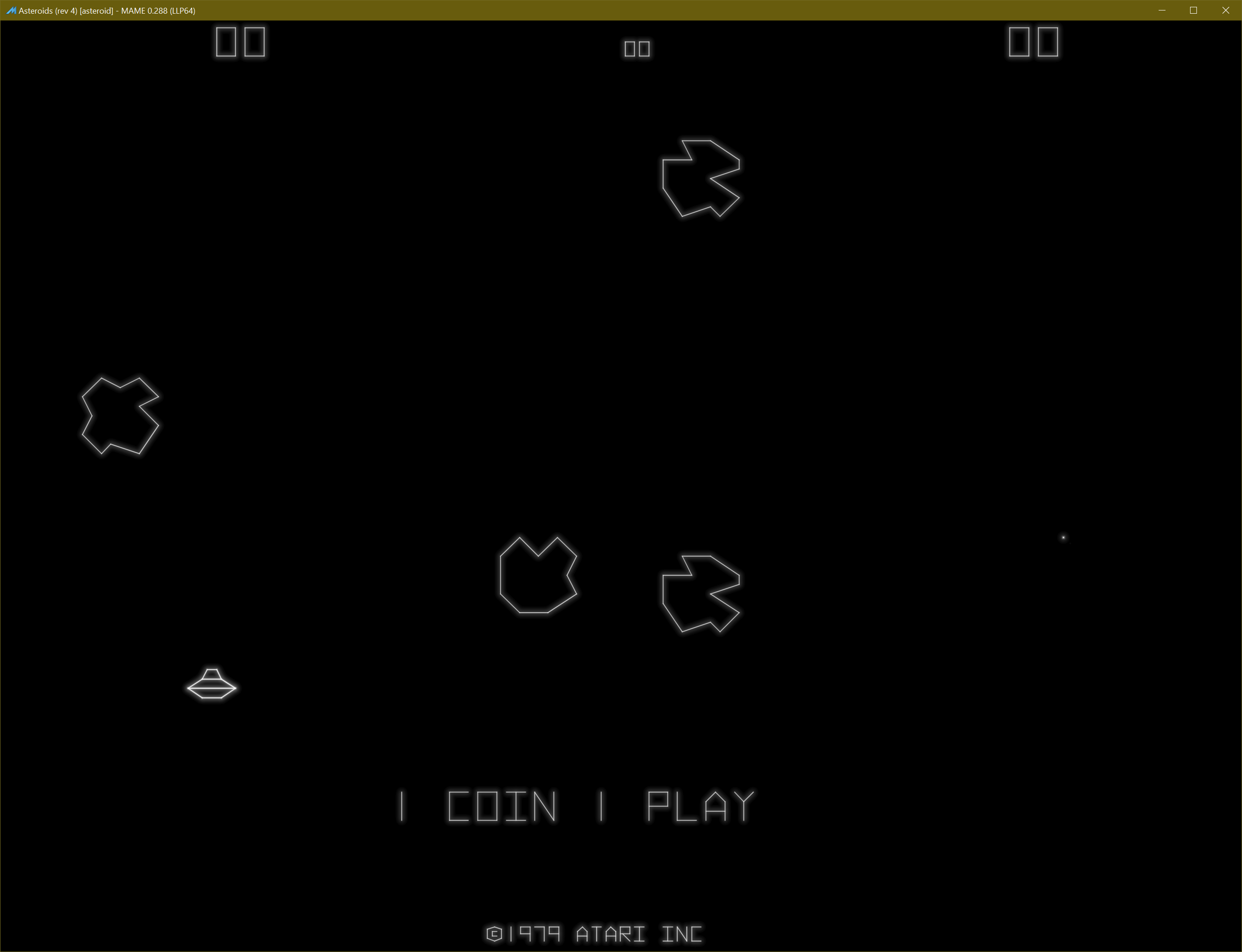
Asteroids (monochrome vector display)
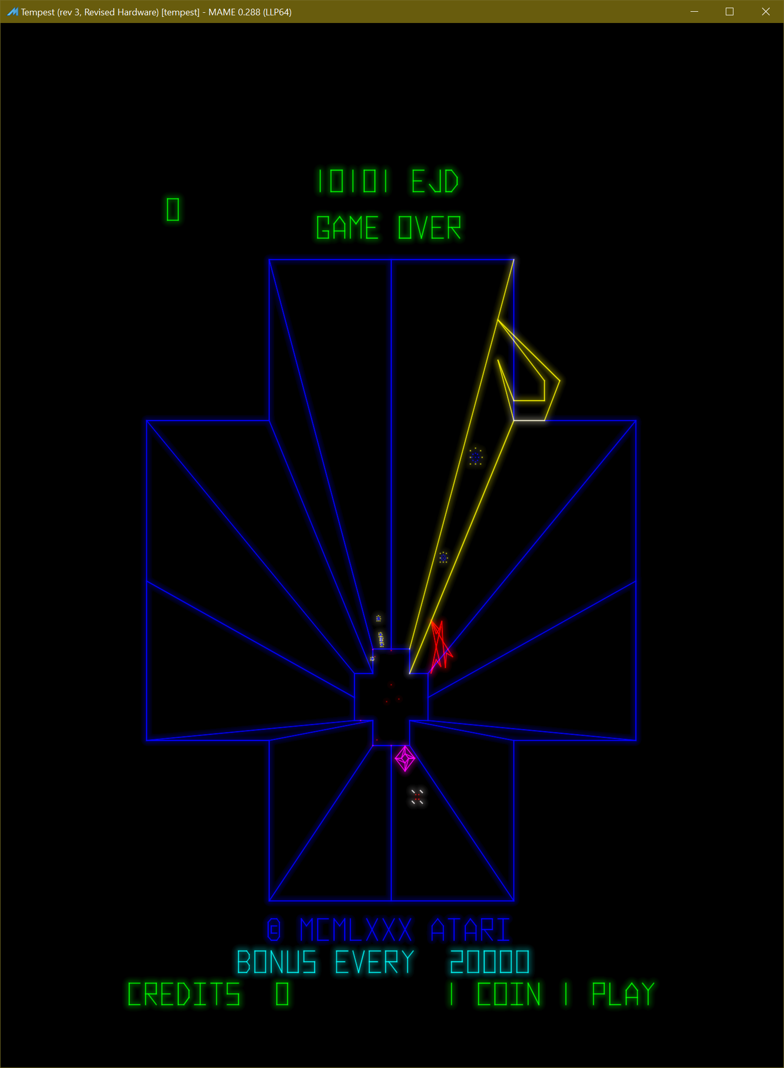
Tempest (colour vector display)
Building and validation
After changing a vector CRT shader, rebuild every supported backend with:
make shaders CHAIN=vector-crt
Expected binary changes appear below
bgfx/shaders/{dx9,dx11,essl,glsl,metal,spirv}/chains/vector-crt/.
Useful validation systems include Asteroids, Battlezone, Tempest, and Star Wars. Check at minimum:
Thin diagonal, horizontal, and vertical vectors for aliasing and equal energy.
Points and short segments for stable round caps and non-zero scan duration.
Bright text for excessive core swelling or halo.
Early and late display-list geometry for subtle scan-order variation.
Pause, reset, state load, rewind, and large emulation-time steps.
1080p and 2160p output for proportional beam width and bloom radius.
Views with artwork for correct screen scaling and composite order.
Current limitations and future work
Potential improvements include:
Hardware-derived timestamps, blanked-move timing, and dwell time.
Independent RGB decay constants and measured phosphor spectra.
Deflection-amplifier slew limits, endpoint ringing, overshoot, and jitter.
Position-dependent focus or convergence.
Measured beam and optical point-spread functions.
HDR-native output and display-aware calibration.
Multi-monitor vector timing and resource ownership.
These extensions should preserve the architecture: the CPU uploads ordered metadata while beam rasterisation, persistence, bloom, and display mapping remain GPU operations.